UV Printer? 3D Printer? HeyGears says “Why Not Both”?
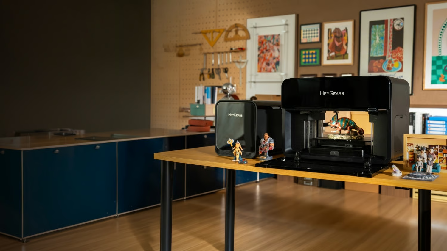
There’s a new contender in the prosumer UV printer world up on Kickstarter, the HeyGears G1. This one’s particularly interesting as they’re explicitly marketing it as being able to produce full-color 3D prints along with the “print-on-anything” functionality we’ve come to expect from a UV flatbed printer.
You get two choices of bed, with the larger being 420 mm x 320 mm x 130 mm. Hardly the largest build volume we’ve seen around here. You can fill that with up to 6 KG of UV ink/resin from its Epson-brand head in glorious full color and layers as small as 10 um. The ink isn’t super cheap — the CMYK kit looks to MRSP at 189 USD — but you aren’t locked in to expensive cartridges at least. HayGears sells ink in bottles, and you’re free to grab any other brand’s bottles if you want to risk it.
The Kickstarter is ongoing, and it will be some time before backers get their printers. But we can report that the early review copies, like the one [Steve Makes Everything] got for the video embedded below, seem to live up to the manufacturer’s claims, which is promising indeed. Certainly the idea of SLA quality without the mess is very appealing to many — though the super-early-bird price of two grand on Kickstarter and the doubtless higher MRSP may temper some of that interest.
If you’re curious about this UV printer business and why a maker might want one that doesn’t do 3D, our own [Tom Nardi] went hands-on with the EufyMake E1 last year.