For many years now, the so-called ‘Blue Pill’ STM32 MCU development board has been a staple in the hobbyist community. Finding its origins as an apparent Maple Mini clone, the diminutive board is easily to use in breadboard projects thanks to its dual rows of 0.1″ pin sockets. Best of all, it only costs a few bucks, even if you can only really buy it via sellers on AliExpress and EBay.
Starting last year, boards with a black soldermask and an STM32F4 Access (entry-level) series MCUs including the F401 and F411 began to appear. These boards with the nickname ‘Black Pill’ or ‘Black Pill 2’. F103 boards also existed with black soldermask for a while, so it’s confusing. The F4xx Black Pills are available via the same sources as the F103-based Blue Pill ones, for a similar price, but feature an MCU that’s considerably newer and more powerful. This raises the question of whether it makes sense at this point to switch to these new boards.
Our answer is yes, but it’s not entirely clearcut. The newer hardware is better for most purposes, really lacking only the F103’s dual ADCs. But hardware isn’t the only consideration; depending on one’s preferred framework, support may be lacking or incomplete. So let’s take a look at what it takes to switch.
The Hardware
The F4 MCUs have significantly better specs than the F103, with a higher clockspeed, more flash storage and more SRAM. In total we have three MCUs to compare on the old and new boards:
- F103: 72 MHz, 64/128 kB Flash, 20 kB SRAM. (STM32F103C8T6)
- F401: 84 MHz, 256 kB Flash, 64 kB SRAM. (STM32F401CCU6)
- F411: 100 MHz, 512 kB Flash, 128 kB SRAM. (STM32F411CEU6)
The Cortex-M core in the F103 is the M3, whereas the F4xx has an M4 core. For the CPU side of the MCU this effectively means that in addition to higher clockspeeds we also get the ARMv7E-M ISA, instead of the ARMv7-M of the M3. This adds full saturation arithmetic instructions, DSP instructions and optional single-precision floating point instructions. Both the F401 and F411 have a single-point FP unit, and are thus much more suited for floating point arithmetic than the F103.
More detailed differences can be found when we look at Application Note 4904 (AN4904) from ST: Migration of microcontroller applications from STM32F1 Series to STM32F4 Access lines. This document summarizes all of the differences between the two MCU families worthy of note when migrating from one to the other, whether for the physical pin layout, peripherals or the bootloader.
Here the biggest changes are probably in the memory layout, along with the number of certain types of peripherals. Feel free to compare along with us in the block diagrams.
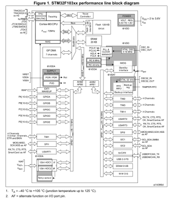
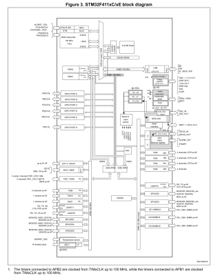
A significant change between F103 and F4xx is that the GPIO peripherals were moved off the Advanced Peripheral Bus (APB) onto the AHB. AHB is the high-performance bus, for high bandwidth, low-latency operations. It is connected directly to the Cortex-M core via the AHB bus matrix. The APB on the other hand is a simpler bus, with no burst operations. Accessing peripherals on the APB from the Cortex-M core requires that the instructions pass over the AHB-to-APB bridge to the APB.
This should mean that GPIO operations are faster on the F4xx MCUs, especially with high-frequency operations. In addition, the I/O pin multiplexing on the F4xx MCUs changed to only allow one alternate function (AF) to be defined for a single GPIO pin. This corresponds to the integration of AF registers in the GPIO peripheral.
A big change is also seen in the RTC peripheral, which on the STM32F1 family is a simple 32-bit counter with programmable prescaler and an alarm register. On the STM32F4xx the RTC peripheral implements a full calendar, with sub-seconds, seconds, minutes, hours, days, months and years. It also has an alarm which can be triggered by any of these calendar fields, as well as an event time-stamp feature and a digital calibration circuit.
While DMA, the FLASH interface and Interrupts also see some changes, these are fairly minor and only of relevance when doing bare-metal programming. The one real gotcha with the F4xx chips is that in place of two 12-bit ADCs with 16 shared channels, the F401 and F411 have a single 12-bit ADC. For the trade, the ADC is marginally faster on the F4xx (2.4 Msps versus 2 Msps on the F103) and has a lower minimum voltage supply requirement of 1.7 V -1.8 V.
The Pills
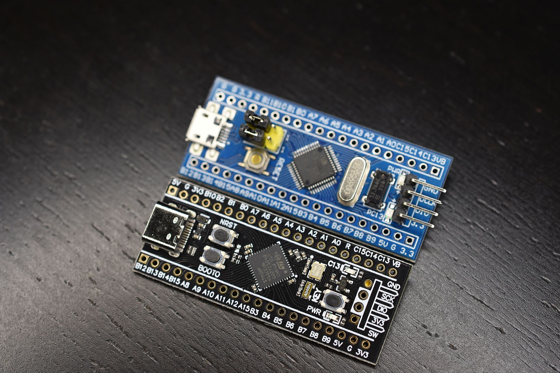
The differences between the two boards are quite stark, even beyond the soldermask color. The board which I am comparing with here is the STM32F411 version, which incidentally seems to be the most popular version when I searched for these boards on the German Amazon website.
The USB connector changed from micro USB-B to USB-C, the MCU package is a 48-pin UFQFPN instead of a 48-pin LQFP, we get an extra user button, and the HSE and LSE oscillators are much smaller. The boot mode pins are gone, but we get a boot mode button instead. We keep the same user-controlled LED on PC13, but the pin-out on the sides of the boards are not 100% compatible. Finally, one ‘Ground’ pin has been replaced with a 5 V pin. (!)
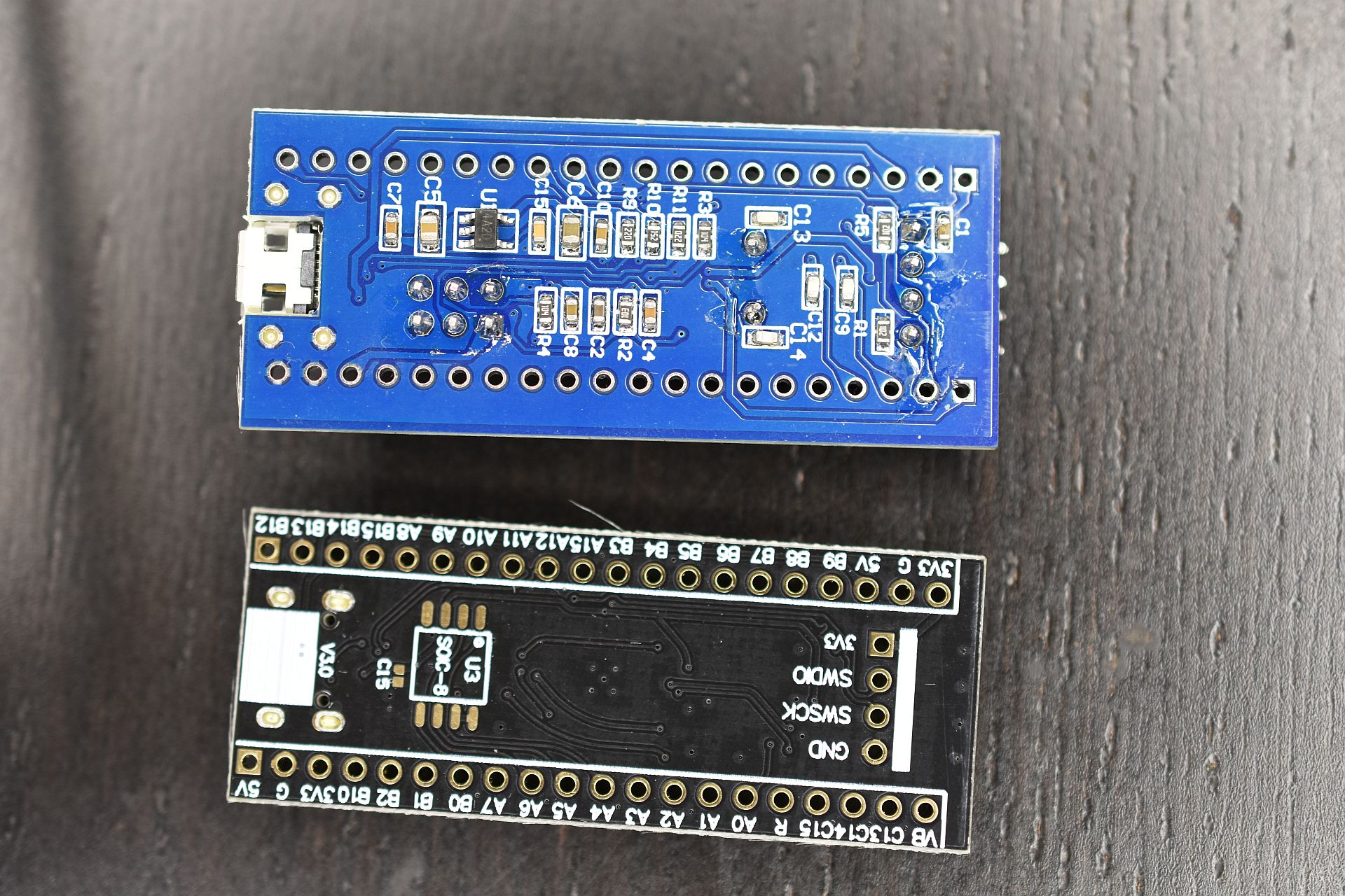
Flipping the boards over, the F103 board features a heap of passives and one IC, while the F411 board is clean except for a footpring for an SPI ROM footprint that fits an W25Q32JVSSIQ 32 Mbit SPI Flash ROM, for instance. This could be used to add a configuration ROM or similar.
Beyond these differences, programming and debugging the board stays the same. One can use serial programming, with genuine STM32 MCUs, Single Wire Debug (SWD) via the four-pin break-out header, or the USB port if a suitable bootloader is installed. The schematic for the board is also available, which refers to the board as the ‘MiniF4’. This schematic also reveals without having to pull out the DMM that the user button is connected to PA0 without pull-up or pull-down resistor.
The Software
The STM32F4 family of MCUs is fully supported by ST’s CMSIS F4 device files, as well as its hardware abstraction layer (HAL) framework. Some may prefer to use ST’s STM32CubeMX software to auto-generate the hardware configuration and setup code.
STM32Duino also shows both the F401 and F411 boards to be supported. Those who are more inclined to meddle with tiny non-venomous snakes should be relieved to know that there are multiple MicroPython definitions for the boards, for the F401 and F411, as well this MicroPython board definition for the F411 version of the board. This means that at least as far as Arduino and MicroPython goes, existing code for F103 boards should run with minimal changes on F401 and F411 boards, keeping in mind potential changes to GPIO and AF pins.
In my own Nodate STM32 project I have added a board definition for the F411 board version as well. The fact of the matter is that these ‘Pill’ boards are such basic break-out boards for STM32 MCUs that very little support is needed. Besides the MCU on the board there’s just the LED on PC13 and a switch on PA0 if one’s framework is the type that abstracts such details away.
Conclusion
There comes a time when one has to move on. Considering that the STM32F103 is part of ST’s first-ever generation of Arm Cortex-M-based MCUs should already hint at that the time may have come for the Cortex-M3. As I noted in my recent article on STM32F103 clone chips, the supply of F103 ‘Blue Pill’ boards has recently become flooded with fakes, clones and brazen imitations of the genuine STM32F103. This makes it hard to even get such a board. Unless one is ready to validate and accept certain of these (admittedly quite good) F103 clone MCUs.
Meanwhile these F401/F411-based ‘Black Pill’ boards do not seem to have any issues with clones or fakes so far, cost roughly the same per unit as the older F103 ‘Blue Pill’, and unless you absolutely need the second ADC unit, are a better deal all-around. Software support should pose no obstacles either, with even details like the user LED using the exact same pin.
Just make sure that that you keep the slightly different pin-out of the F4xx boards in mind (i.e. the new 5 V pin), and double-check against the F401 or F411 reference manual to ensure that the peripherals one uses in a project are still on the same pins after recompiling for the new board. For new projects, using these new boards seems like a no-brainer, which is why I’m pretty sure that I’ll be stocking up on them.
What will your stockpile of cheap STM32 development boards look like the coming years? Will you be switching to F4 MCUs, or sticking with those F103 boards, if only because you bought 75 of them in an auction once and still haven’t used them up? Do you have any special use cases that make the F103 more suitable for your projects? Please let us know in the comments.


No comments:
Post a Comment