You don’t see them much anymore, but there was a time when any hobbyist who dealt with RF probably had a grid dip meter. The idea was to have an oscillator and measure the grid current as it coupled to external circuits. At resonance, the grid current would go down or dip, hence the name. In the hands of someone who knew how to use it, the meter could measure inductance, capacitance, tuned circuits, antennas, and more. [Thomas] takes a peek inside a homebrew unit from the 1950s in a recent video you can see below.
These meters often have a few things in common. They usually have a plug-in coil near the top and a big tuning capacitor. Of course, there’s also a meter. You have to pick the right coil for the frequency of interest, which both sets the oscillator frequency range and couples to the circuit under test.
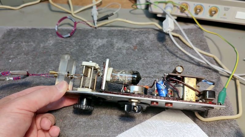
The device has an odd case for a homebrew instrument. Whoever made it was an excellent metalworker. Inside was a neatly built circuit with an EC-81 triode and a unique selenium rectifier.
It would be nice to know who the unknown builder was, but with a bit of coaxing, the device still worked just fine. Of course, these days, you have many better options, but it is amazing what all this relatively simple device could do.
We’ve covered how these meters work before, including some pictures from our own benches.


No comments:
Post a Comment